Multimeters are used for a variety of tasks and can provide crucial information when you’re wiring something in or diagnosing a device. Most commonly, they’re used for measuring voltage, resistance and current, but some multimeters have additional capabilities like diode forward voltage, continuity, capacitance, bipolar junction transistor (BJT) amplification and temperature measurements.
In the hands of someone who knows how to use a multimeter, there is an incredibly small chance of error. Unfortunately, there are instances where accidents can happen. Proper training and paying attention to what you’re doing are vital.
Yes, there is a very small chance of either short circuiting electronics or damaging the multimeter itself. However, these incidents are isolated and are generally because of user error. There are fail-safe systems in place that should mitigate any damage and harm to the user because of a problem with the unit or the measurement itself.
It doesn’t matter if you’re a master electrician or a novice, there are a few things to bear in mind before using some of the functions on a multimeter. Let’s break down some of the features a multimeter has and how they can potentially cause damage.
Features And Hazards Of A Multimeter
We’ll further look at the most common features included with most digital multimeters. While some functions have a greater chance to cause issues than others, they should all be approached with caution.
SPECIAL PRECAUTIONS MUST BE TAKEN WHEN WORKING WITH MAINS ELECTRICITY AND WALL POWER (V~)! I just wanted to emphasize this as mains voltage is dangerous and can lead to fatal injuries.
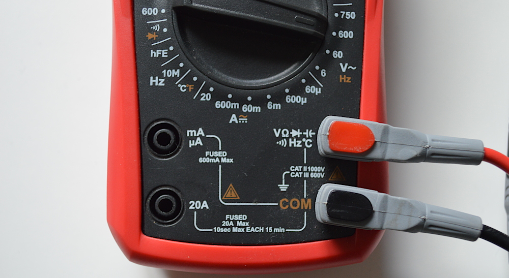
Before any measurements, always check the measurement probes for visual damages (cracking, broken insulation) and if the probes are connected to the correct terminals for the physical quantity (voltage mV, V or current mA, A or resistance Ω) and the appropriate range you are about to measure (see Fig 1.). Damaged probes may cause electrical shock and can lead to fatal injuries!
Measuring Voltage
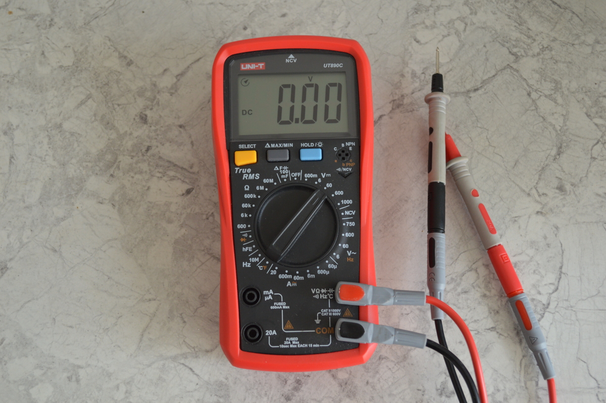
On your digital multimeter, you should see a dial position with the letter V that lets you measure the voltage. For example, in Fig. 2 at the top part I have circled the V⎓ or direct voltage (DC – direct current) measurement setting of my Uni-T UT890C multimeter, but at the bottom – the V~ or alternating voltage (AC – alternating current) setting. The numbers in the measurement setting scale represent the maximum voltage this setting can safely measure (for direct voltage V⎓ the lowest setting is up to 600mV or 0,6V, but the highest range – 1000V). Note that lower ranges always allow for more precise measurements.
On most budget multimeters you have to choose the range for the measurement, but more advanced multimeters come with an automatic range setting. If you are unsure of the maximum value of the voltage you are measuring, start with the highest range.
Pay attention to the voltage you are measuring – DC or AC – so that you can put the test leads into the right terminals of your multimeter and choose the appropriate range setting. At the very least, the multimeter might show improper values, but, in the worst-case scenario, it may cause damage to the multimeter.
In general, it’s also important not to cross the test probes while doing any measurements. Failing to do this could create a short circuit through the probes to the device on which you are working on, which can damage the device.

Measuring Current
The most damage can be done both to the multimeter and the circuit you are measuring when you are incorrectly measuring current or when the multimeter probes are unintentionally left in the terminals for measuring current while measuring voltage (I have personally made this mistake). By incorrectly I mostly mean that the multimeter is not made into an actual part of the circuit, i.e., the multimeter is not connected in series in the electrical circuit, but it must be connected in series. Additionally, damage can be done if the current is bigger than the maximum rating of the multimeter.
Most multimeters are equipped with a fuse, which will blow (disconnect itself from the circuit) or create an open circuit to attempt to protect the device you are working on and the multimeter itself. In this case, you will need to replace the fuse before you can measure current again.
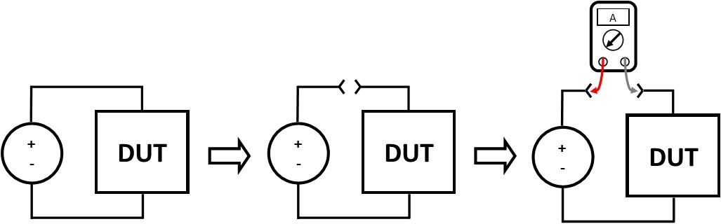
To measure current with a multimeter, first, you must switch off the power to the circuit you are about to modify for current measurement. Then you must “break” the circuit in the place you want to measure the current. Finally, you have to make the multimeter a part of the circuit, i.e., connect it in the place of the break and switch the circuit back on. These steps are illustrated in Fig. 3. Essentially, the current will be going through the multimeter itself as it is closing the circuit and “acting as a short circuit” (in reality, the resistance introduced in the circuit by the multimeter/ammeter or the series resistance will be around a few mΩ, but in most cases it’s negligible and doesn’t affect the measurement result). Remember to connect the measurement probes to the correct terminals for the measurement (current measurement, range)!
Measuring Resistance
Measuring resistance is the function that has the least chance of causing damage. This is because you generally measure the resistance of a de-energized component (out of the circuit). To avoid damage to the multimeter, measure the component’s resistance with the device’s power switched off and its capacitors discharged.
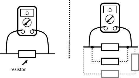
Usually, in circuit measurement of resistance can give incorrect results as other components can influence the result. For example, as can be seen in Fig. 4, if there are connections to other components, the result will be the equivalent resistance of all the involved resistors, therefore the resulting resistance won’t be for the one component you are measuring.
Your multimeter will use the battery inside of the multimeter to generate a small current and push it through the component and use it to calculate the resistance.
Tips For Novice Multimeter Users
Here are some tips that everyone should know to use their multimeter safely:
- Check the probes and make sure the plastic handles aren’t cracking or falling off as well as check the wires of the probes and their insulation. You don’t want to be touching the conductive parts of the probes while you’re performing measurements or you can get an electrical shock.
- Take care when using measurement probes and make sure they don’t touch each other while measuring.
- Be sure to connect the measurement probes in the correct terminals for your measurement and choose the correct range.
- Be cautious when working with high voltage, especially with mains! All it takes is a slip of the wrist to cause an accident. Wear any protective gear if possible.
- Be aware of errant power spikes that can happen when measuring voltage. These can damage electronics.
- Understand what your multimeter can take in terms of voltage spiking. These are established by the CAT rating of your device. Going over these ratings can cause internal damage to the multimeter.
Thanks for reading! I highly appreciate your comments and I’m looking forward to any questions you might have. I will try to answer them as soon as possible.
Leave a Reply